Assumptions:
- Plane sections of the beam, originally plane, remain plane.
- The material of the beam is homogeneous and obeys Hooke’s law.
- The moduli of elasticity for tension and compression are equal.
- The beam is initially straight and of constant cross-section.
- The plane of loading must contain a principle axis of the beam cross-section and the loads must be perpendicular to the longitudinal axis of the beam.
FLEXURE FORMULA:
Where M= bending moment
I = moment of inertia of the section about the bending axis.
E = Young’s Modulus of the material of the beam.
R = radius of curvature of the bent beam.
If y is replaced by c, the distance to remotest element, then
Where, Z= section modulus and is given by 
PURE AND NON-UNIFORM BENDING:
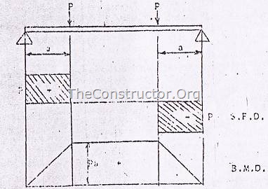
Pure bending refers to flexure of a beam under constant bending moment, which means that the shear force is zero.
i.e 
In contrast, non-uniform bending refers to flexure in the presence of shear forces, which means that the bending moment changes as we move along the axis of the beam.
Examples of beams in pure bending:
(a) Beam subjected to positive bending moments (figure 1)

Figure 1
(b) Beam with central region in pure bending (figure 2)

Figure 2
NORMAL STRAINS:
As a result of bending, somewhere between the top and bottom of the beam is a surface in which the longitudinal fibres do not change in length. This surface is called the neutral surface of the beam and its intersection with any cross-sectional plane is called the neutral axis of the cross-section.
All the longitudinal fibres other than those in the neutral surface either lengthen or shorten, thereby creating longitudinal strains  .
.
Where k = curvature = 1/R
This equation shows longitudinal strains are proportional to the curvature and that they vary linearly with the distance y from the neutral surface. This equation is derived from the geometry of the deformed beam and is independent of the properties of the material. The equation is valid irrespective of the stress-strain diagram of the material.
TRANSVERSE STRAIN:
The axial strains ![clip_image009[1] clip_image009[1]](http://theconstructor.org/wp-content/uploads/2010/09/clip_image00913.gif) are accompanied by lateral or transverse strains due to the effect of Poisson’s ratio. Positive strains are accompanied by negative transverse strains
are accompanied by lateral or transverse strains due to the effect of Poisson’s ratio. Positive strains are accompanied by negative transverse strains  .
.
Where  is the Poisson’s Ratio.
As a result of these strains, the shape of the cross-section change. For example, let us study the case of a beam of rectangular cross-section subjected to pure bending so as to induce tension at the top and compression at the bottom. The sides of the rectangular cross-section become inclined to each other. The top surface becomes saddle shaped. If the longitudinal curvature in the xy plane is considered positive, then the transverse curvature in the yz plane is negative. All planes of the beam that were initially parallel to neutral surface develop antiplastic curvature.
APPLICABILITY OF FLEXURE FORMULA:
The normal stresses determined from flexure formula concern pure bending, which means no shear forces act on the cross-section. In case of non-uniform bending the presence of shear forces produces warping or put of place distortion of the cross-section, thus, a section that is plane before bending is no longer plane after bending. Warping due to shear greatly complicates the behaviour of the beam, but more elaborate analysis shows that the normal stresses calculated from the flexure formula are not significantly altered by the presence of the shear stresses and the associated warping. Thus use of the theory of pure bending for calculating normal stresses in cases of non-uniform bending is considered justified.
ULTIMATE STRENGTH IN BENDING:
When a beam is loaded upto failure, then using bending moment at failure, flexural stress is calculated and is called Modulus of Rupture. it is used to compare the ultimate strength of beams of various sizes and materials.