Below are simple instructions on how to calculate the bending moment diagram of a simple supported beam. Study this method as it is very versatile (and can be adapted to many different types of problem. The ability to calculate the bending moment of a beam is very common practice for structural engineers and often comes up in college and high school exams.
Firstly, what is a Bending Moment? A moment is rotational force that occurs when a force is applied perpendicularly to a point at a given distance away from that point. It is calculated as the perpendicular force multiplied by the distance from the point. A Bending Moment is simply the bend that occurs in a beam due to a moment. It is important to remember two things when calculating bending moments; (1) the standard units are Nm and (2) clockwise bending is taken as negative. Anyways, with the boring definitions out of the way, let's look at the steps to calculate a bending moment diagram:
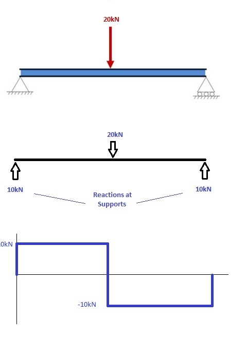
1. Calculate reactions at supports and draw Free Body Diagram (FBD).
If not sure how to do this, click here for out tutorial. Once you have the reactions, draw your Free Body Diagram andShear Force Diagram underneath the beam:
2. From left to right, make "cuts" before and after each reaction/load
TO calculate the bending moment of a beam, we must work in the same way we did for the Shear Force Diagram. Starting at x = 0 we will move across the beam and calculate the bending moment at each point.
Cut 1
Make a "cut" just after the first reaction of the beam. In our simple example:
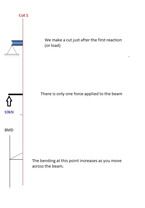
So, when we cut the beam, we only cosider the forces that are applied to the left of our cut. In this case we have a 10kN force in the upward direction. Now as you recall, a bending moment is simply the force x distance. So as we move further from the force, the magnitude of the bending moment will increase. We can see this in our BMD. The equation for this part of our bending moment diagram is:
-M(x) = 10(-x)
M(x) = 10x
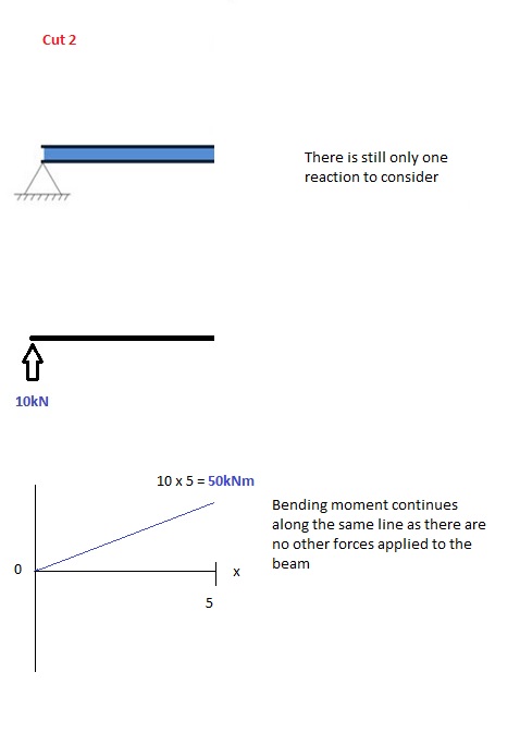
Cut 2
This cut is made just before the second force along the beam. Since there are no other loads applied between the first and second cut, the bending moment equation will remain the same. This means we can calculate the maximum bending moment (in this case at the midpoint, or x = 5) by simply substituting x=5 into the above equation:
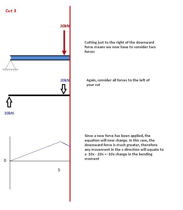
Cut 3
This cut is made just after the second force along the beam. Now we have TWO forces that act to the left of our cut: a 10kN support reaction and a -20kN downward acting load. So now we must consider both these forces as we progress along our beam. For every metre we move across the beam, there will a +10kNm moment added from the first force and -20kNm from the second. So after the point x=5, our Bending Moment Equation becomes:
M(x) = 50 +10(x-5) - 20(x-5)
M(x) = 50 -10(x-5) for 5 ≤ x ≤ 10
NOTE: The reason we write (x-5) is because we want to know the distance from the pt x=5 only. Anything before this point uses a previous equation.
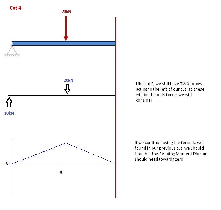
Cut 4
Again, let's move across to the right of our beam and make a cut just before our next force. In this case, our next cut will occur just before the reaction from Right Support. Since there are no other forces between the support and our previous cut, the equation will remain the same:
M(x) = 50 -10(x-5) for 5 ≤ x≤ 10
And let's substitute x=10 into this to find the find bending moment at the end of the beam:
M(x) = 50 - 10(10-5) = 0kNm
This makes perfect sense. Since our beam is static (and not rotation) it makes sense that our beam should have zero moment at this point when we consider all our forces. It also satisfies one of our initial conditions, that the sum of moments at a support is equal to zero. NOTE: If your calculations lead you to any other number other than 0, you have made a mistake!
 |