This article is part of the solid mechanics course, aimed at engineering students. Please leave feedback in the discussion section above.
Contents
- 1 What is shear force?
- 2 Basic shear diagram
- 3 Basic bending moment diagram
- 4 Point moments
- 5 Uniformly Distributed Load (UDL)
- 5.1 Shear force diagram
- 5.2 Bending moment diagram
- 5.2.1 Hypothetical scenario
What is shear force?
Below a force of 10N is exerted at point A on a beam. This is an external force. However because the beam is a rigid structure,the force will be internally transferred all along the beam. This internal force is known as shear force. The shear force between point A and B is usually plotted on a shear force diagram. As the shear force is 10N all along the beam, the plot is just a straight line, in this example. The idea of shear force might seem odd, maybe this example will help clarify. Imagine pushing an object along a kitchen table, with a 10N force. Even though you're applying the force only at one point on the object, it's not just that point of the object that moves forward.The whole object moves forward, which tells you that the force must have transferred all along the object, such that every atom of the object is experiencing this 10N force.
Please note that this is not the full explanation of what shear force actually is.Basic shear diagram
What if there is more than one force, as shown in the diagram below, what would the shear force diagram look like then?
The way you go about this is by figuring out the shear force at points A,B,C,E (as there is an external force acting at these points). The way you work out the shear force at any point, is by covering (either with your hand or a piece of paper), everything to right of that point, and simply adding up the external forces. Then plot the point on the shear force diagram. For illustration purposes, this is done for point D: Shear force at D = 10N - 20N + 40N = 30Newtons
 Now, let's do this for point B. BUT - slight complication - there's a force acting at point B, are you going to include it? The answer is both yes and no. You need to take 2 measurements. Firstly put your piece of paper, so it's JUST before point B:
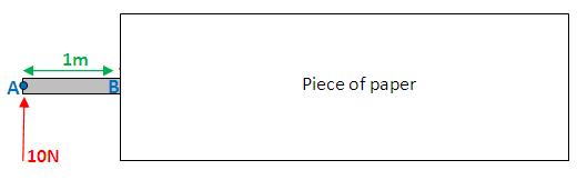 Shear force at B = 10N
 Now place your paper JUST after point B:
 Shear force at B = 10N - 20N = -10N
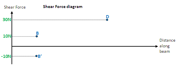 (B' is vertically below B)Now, do point A, D and E, and finally join the points. your diagram should look like the one below. If you don't understand why, leave a message on the discussion section of this page (its at the top), I will elaborate on the explanation:
 Notice how nothing exciting happens at point D, which is why you wouldn't normally analyse the shear force at that point. For clarity, when doing these diagrams it is recommended you move you paper from left to right, and hence analyse points A,B, C, and E, in that order. You can also do this procedure covering the left side instead of the right, your diagram will be "upside down" though. Both diagrams are correct.
Basic bending moment diagram
Bending moment refers to the internal moment that causes something to bend. When you bend a ruler, even though apply the forces/moments at the ends of the ruler, bending occurs all along the ruler, which indicates that there is a bending moment acting all along the ruler. Hence bending moment is shown on a bending moment diagram. The same case from before will be used here:To work out the bending moment at any point, cover (with a piece of paper) everything to the right of that point, and take moments about that point. (I will take clockwise moments to be positive). To illustrate, I shall work out the bending moment at point C: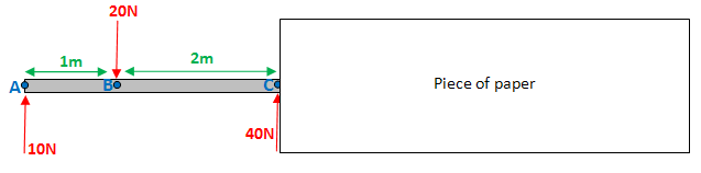 Bending moment at C = 10Nx3m - 20Nx2m = -10Nm
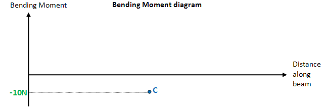 Notice that there's no need to work out the bending moment "just before and just after" point C, (as in the case for the shear force diagram). This is because the 40N force at point C exerts no moment about point C, either way.Repeating the procedure for points A,B and E, and joining all the points:
 Normally you would expect the diagram to start and end at zero, in this case it doesn't. This is my fault, and it happened because I accidentally chose my forces such that there is a moment disequilibrium. i.e. take moments about any point (without covering the right of the point), and you'll notice that the moments aren't balanced, as they should be. It also means that if you're covering the left side as opposed to the right, you will get a completely different diagram. Sorry about this...
Point moments
Point moments are something that you may not have come across before. Below, a point moment of 20Nm is exerted at point C. Work out the reaction of A and D: Force equilibrium: R1 + R2 = 40Taking moments about A (clockwise is positive): 40·2 - 20 - 6·R2 = 0R1 = 30N , R2 = 10NIf instead you were to take moments about D you would get: - 20 - 40·4 + 6·R1 = 0I think it's important for you to see that wherever you take moments about, the point moment is always taken as a negative (because it's a counter clockwise moment).So how does a point moment affect the shear force and bending moment diagrams?
Well. It has absolutely no effect on the shear force diagram. You can just ignore point C when drawing the shear force diagram. When drawing the bending moment diagram you will need to work out the bending moment just before and just after point C: Just before: bending moment at C = 3·30 - 1·40 = 50NmJust after: bending moment at C = 3·30 - 1·40 - 20 = 30NmThen work out the bending moment at points A, B and D (no need to do before and after for these points). And plot.Cantilever beamUntil now, you may have only dealt with "simply supported beams" (like in the diagram above), where a beam is supported by 2 pivots at either end. Below is a cantilever beam, which means - a beam that rigidly attached to a wall. Just like a pivot, the wall is capable of exerting an upwards reaction force R1 on the beam. However it is also capable of exerting a point moment M1 on the beam.
 Force equilibrium: R1 = 10NTaking moments about A: -M1 + 10·2 = 0 → M1 = 20Nm


