There are two types of transmission media :
- Guided
- Unguided
Guided Media :
- Unshielded Twisted Pair (UTP)
- Shielded Twisted Pair
- Coaxial Cable
- Optical Fiber
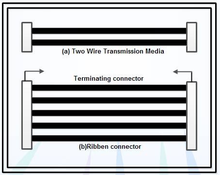
Two-wire Open Lines
The
simplest transmission media is a two-wire transmission line. There are
two wires insulated from each other, open to free space. This type of
media is suitable for connecting equipments that are separated less than
50 meters. This media can support data rate up to a theoretical maximum
of 19 Kbps. A two-wire transmission media can directly connect two
computers. However, if a computer
is to be connected to a communicating device like a modem, multiple
communication lines are required. In this case, a number of separate
insulated wires are moulded in the form of a flat ribbon with
terminating connectors as shown in Figure (b).
The
limitations of this transmission media are their poor noise
characteristics, failure to provide connectivity over long distances,
low bit rate. This type of transmission media is often used in telephone
networks.
Unshielded Twisted Pair (UTP) : UTP
is the copper media, inherited from telephony, which is being used for
increasingly higher data rates, and is rapidly becoming the de facto
standard for horizontal wiring, the connection between, and including,
the outlet and the termination in the communication closet.
A Twisted Pair is
a pair of copper wires, with diameters of 0.4-0.8 mm, twisted together
and wrapped with a plastic coating. The twisting increases the
electrical noise immunity, and reduces the bit error rate (BER) of the
data transmission. A UTP cable contains from 2 to 4200 twisted pairs.

UTP
is a very flexible, low cost media, and can be used for either voice or
data communications. Its greatest disadvantage is the limited
bandwidth, which restricts long distance transmission with low error
rates.
Shielded Twisted Pair (STP) : STP
is heavier and more difficult to manufacture, but it can greatly
improve the signaling rate in a given transmission scheme Twisting
provides cancellation of magnetically induced fields and currents on a
pair of conductors.
Magnetic
fields arise around other heavy current-carrying conductors and around
large electric motors. Various grades of copper cables are available,
with Grade 5 being the best and most expensive.
Grade
5 copper, appropriate for use in 100-Mbps applications, has more twists
per inch than lower grades. More twists per inch means more linear feet
of copper wire used to make up a cable run, and more copper means more
money.
Shielding
provides a means to reflect or absorb electric fields that are present
around cables. Shielding comes in a variety of forms from copperbraiding
or copper meshes to aluminized.
Mylar tape wrapped around each conductor and again around the twisted pair.
Coaxial Cable: Coaxial
cable is a two-conductor cable in which one conductor forms an
electromagnetic shield around the other. The two conductors are
separated by insulation. It is a constant impedance transmission cable.
This media is used in base band and broadband transmission. Coaxial
cables do not produce external electric and magnetic fields and are not
affected by them. This makes them ideally suited, although more
expensive, for transmitting signals.
Optical Fiber : Optical
fiber consists of thin glass fibers that can carry information at
frequencies in the visible light spectrum and beyond. The typical
optical fiber consists of a very narrow strand of glass called the core.
Around the core is a concentric layer of glass called the cladding.
A
typical core diameter is 62.5 microns .Typically cladding has a
diameter of 125 microns. Coating the cladding is a protective coating
consisting of plastic, it is called the Jacket. An important
characteristic of fiber optics is refraction. Refraction is the
characteristic of a material to either pass or reflect light. When light
passes through a medium, it “bends” as it passes from one medium to the
other. An example of this is when we look into a pond of water If the
angle of incidence is small, the light rays are reflected and do not
pass into the water.
If
the angle of incident is great, light passes through the media but is
bent or refracted. Optical fibers work on the principle that the core
refracts the light and the cladding reflects the light. The core
refracts the light and guides the light along its path. The cladding
reflects any light back into the core and stops light from escaping
through it - it bounds the medium!
Unguided Media : Transmission
media then looking at analysis of using them unguided transmission
media is data signals that flow through the air. They are not guided or
bound to a channel to follow. Following are unguided media used for data
communication :
- Radio Transmission
- Microwave
- Satellite Communication
. RF Propagation : There are three types of RF (radio frequency) propagation :
- Ground Wave
- Ionospheric
- Line of Sight (LOS)
Ground
wave propagation follows the curvature of the Earth. Ground waves have
carrier frequencies up to 2 MHz. AM radio is an example of ground wave
propagation. Ionospheric propagation bounces off of the Earth’s
ionospheric layer in the upper atmosphere.
It
is sometimes called double hop propagation. It operates in the
frequency range of 30 - 85 MHz. Because it depends on the Earth’s
ionosphere, it changes with the weather and time of day. The signal
bounces off of the ionosphere and back to earth. Ham radios operate in
this range.
Line
of sight propagation transmits exactly in the line of sight. The
receive station must be in the view of the transmit station. It is
sometimes called space waves or tropospheric propagation. It is limited
by the curvature of the Earth for ground-based stations (100 km, from
horizon to horizon). Reflected waves can cause problems. Examples of
line of sight propagation are: FM radio, microwave and satellite.
Radio Frequencies : The
frequency spectrum operates from 0 Hz (DC) to gamma rays (1019 Hz).
Radio frequencies are in the range of 300 kHz to 10 GHz. We are seeing
an emerging technology called wireless LANs. Some use radio frequencies
to connect the workstations together, some use infrared technology.
Microwave : Microwave
transmission is line of sight transmission. The transmit station must
be in visible contact with the receive station. This sets a limit on the
distance between stations depending on the local geography. Typically
the line of sight due to the Earth’s curvature is only 50 km to the
horizon! Repeater stations must be placed so the data signal can hop,
skip and jump across the country.
Microwaves
operate at high operating frequencies of 3 to 10 GHz. This allows them
to carry large quantities of data due to their large bandwidth.
Advantages :
(a) They require no right of way acquisition between towers.
(b) They can carry high quantities of information due to their high operating frequencies.
(c) Low cost land purchase: each tower occupies only a small area.
(d) High frequency/short wavelength signals require small antennae.
Disadvantages :
(a) Attenuation by solid objects: birds, rain, snow and fog.
(b) Reflected from flat surfaces like water and metal.
(c) Diffracted (split) around solid objects.
(d) Reflected by atmosphere, thus causing beam to be projected away from receiver.
Satellite : Satellites
are transponders (units that receive on one frequency and retransmit on
another) that are set in geostationary orbits directly over the
equator. These geostationary orbits are 36,000 km from the Earth’s
surface. At this point, the gravitational pull of the Earth and the
centrifugal force of Earth’s rotation are balanced and cancel each other
out. Centrifugal force is the rotational f0000000orce placed on the
satellite that wants to fling it out into space.
The
uplink is the transmitter of data to the satellite. The downlink is the
receiver of data. Uplinks and downlinks are also called Earth stations
because they are located on the Earth. The footprint is the “shadow”
that the satellite can transmit to, the shadow being the area that can
receive the satellite’s transmitted signal.
