3. Strains
Strain is defined a the ratio of change in dimension to original dimension of a body when it is deformed. It is a dimensionless quantity as it is a ratio between two quantities of same dimension.
|
3.1. Linear Strain
Linear strain of a deformed body is defined as the ratio of the change in length of the body due to the deformation to its original length in the direction of the force. If l is the original length and dl the change in length occurred due to the deformation, the linear strain e induced is given by e=dl/l. 
Linear strain may be a tensile strain, et or a compressive strain ec according as dl refers to an increase in length or a decrease in length of the body. If we consider one of these as +ve then the other should be considered as –ve, as these are opposite in nature.
|
Showing posts with label Mechanics of structure. Show all posts
Showing posts with label Mechanics of structure. Show all posts
Strength of Materials - Strains
Angle of repose
The angle of repose or the critical angle of repose,of a granular material is the steepest angle of descent or dip relative to the horizontal plane to which a material can be piled without slumping. At this angle, the material on the slope face is on the verge of sliding. The angle of repose can range from 0° to 90°. Smooth, rounded sand grains cannot be piled as steeply as can rough, interlocking sands. If a small amount of water is able to bridge the gaps between particles, electrostatic attraction of the water to mineral surfaces will increase soil strength.
Parts of a roof truss
A roof truss is an engineered panel made up of triangular parts. Set out below are the main structural components and fixing points in a standard 'A' type truss.
- Apex
- Apex plate
- Top chord
- Heel plate
- 1/3 point plate
- Bottom chord
- Slice plate
- Heel
- 1/4 point plate
- Web
- Nominal span
- Overhang

Euler's Column Formula
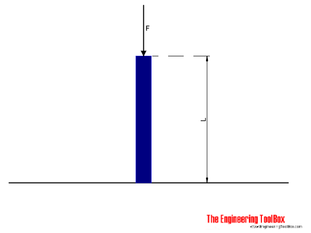 Columns fail by buckling when their critical load is reached. Long columns can be analysed with the Euler column formula
F = n π2 E I / L2 (1)
where
F = allowable load (lb, N)
n = factor accounting for the end conditions
E = modulus of elastisity (lb/in2, Pa (N/m2))
L = length of column (in, m)
I = Moment of inertia (in4, m4)
Factor Counting for End Conditions
- column pivoted in both ends : n = 1
Lateral earth pressure
Lateral earth pressure is the pressure that soil exerts in the horizontal direction. The lateral earth pressure is important because it affects the consolidation behavior and strength of the soil and because it is considered in the design of geotechnical engineering structures such as retaining walls, basements, tunnels, deep foundations and braced excavations.
The coefficient of lateral earth pressure, K, is defined as the ratio of the horizontaleffective stress, σ’h, to the vertical effective stress, σ’v. The effective stress is the intergranular stress calculated by subtracting the pore pressure from the total stress as described in soil mechanics. K for a particular soil deposit is a function of the soil properties and the stress history. The minimum stable value of K is called the active earth pressure coefficient, Ka; the active earth pressure is obtained, for example,when a retaining wall moves away from the soil. The maximum stable value of K is called the passive earth pressure coefficient, Kp; the passive earth pressure would develop, for example against a vertical plow that is pushing soil horizontally. For a level ground deposit with zero lateral strain in the soil, the "at-rest" coefficient of lateral earth pressure, K0 is obtained.
Types of Supports
Roller Supports Roller supports are free to rotate and translate along the surface upon which the roller rests. The surface may be horizontal, vertical or slopped at any angle. Roller supports are commonly located at one end of long bridges in the form of bearing pads. This support allows bridge structure to expand and contract with temperature changes and without this expansion the forces can fracture the supports at the banks. This support cannot provide resistance to lateral forces. Roller support is also used in frame cranes in heavy industries as shown in figure, the support can move towards left, right and rotate by resisting vertical loads thus a heavy load can be shifted from one place to another horizontally. Roller supports are free to rotate and translate along the surface upon which the roller rests. The surface may be horizontal, vertical or slopped at any angle. Roller supports are commonly located at one end of long bridges in the form of bearing pads. This support allows bridge structure to expand and contract with temperature changes and without this expansion the forces can fracture the supports at the banks. This support cannot provide resistance to lateral forces. Roller support is also used in frame cranes in heavy industries as shown in figure, the support can move towards left, right and rotate by resisting vertical loads thus a heavy load can be shifted from one place to another horizontally. | |
Hinge mec
The hinge support is capable of resisting forces acting in any direction of the plane. This support does not provide any resistance to rotation. The horizontal and vertical component of reaction can be determined using equation of equilibrium. Hinge support may also be used in three hinged arched bridges at the banks supports while at the center internal hinge is introduced. It is also used in doors to produce only rotation in a door.
| |
Columns and strut - Euler and Rankine's formulae
Difference between a column and a strut:
You have to understand the concept of effective length, least radius of gyration and slenderness ratio first to calculate the Euler's buckling load.
We see the columns everywhere around us because they are very important component of structures. Column is the vertical member of a structure which generally takes the compression from the other components mainly, slabs. So the main function is to transfer the vertical load to the lower foundations of the structure. There is other component which is known as the strut, it is again a compression member which takes up the compression or also they may be designed to take up the tension, such members are used in the roof trusses.
The major structural difference: Columns have higher slenderness ratio so, due to more slenderness the columns fail due to buckling in general and the struts fail due to crushing under the action of the compression.
You have to understand the concept of effective length, least radius of gyration and slenderness ratio first to calculate the Euler's buckling load.
THEORY OF SIMPLE BENDING
Assumptions:
- Plane sections of the beam, originally plane, remain plane.
- The material of the beam is homogeneous and obeys Hooke’s law.
- The moduli of elasticity for tension and compression are equal.
- The beam is initially straight and of constant cross-section.
- The plane of loading must contain a principle axis of the beam cross-section and the loads must be perpendicular to the longitudinal axis of the beam.
FLEXURE FORMULA:

Where M= bending moment
I = moment of inertia of the section about the bending axis.
 =fibre stress at a distance ‘y’ from the centroidal/neutral axis.
E = Young’s Modulus of the material of the beam.
How to Calculate the Bending Moment Diagram of a Beam
Below are simple instructions on how to calculate the bending moment diagram of a simple supported beam. Study this method as it is very versatile (and can be adapted to many different types of problem. The ability to calculate the bending moment of a beam is very common practice for structural engineers and often comes up in college and high school exams.
Firstly, what is a Bending Moment? A moment is rotational force that occurs when a force is applied perpendicularly to a point at a given distance away from that point. It is calculated as the perpendicular force multiplied by the distance from the point. A Bending Moment is simply the bend that occurs in a beam due to a moment. It is important to remember two things when calculating bending moments; (1) the standard units are Nm and (2) clockwise bending is taken as negative. Anyways, with the boring definitions out of the way, let's look at the steps to calculate a bending moment diagram:
1. Calculate reactions at supports and draw Free Body Diagram (FBD).
If not sure how to do this, click here for out tutorial. Once you have the reactions, draw your Free Body Diagram andShear Force Diagram underneath the beam:  |
Various types of Roof trusses for various spans
What is a Truss?
- In Architecture and Structural Engineering, a truss is a structure comprising one or more triangular units constructed with straight slender members whose ends are connected at joints referred to as nodes.
- External forces and reactions to those forces are considered to act only at the nodes and result in forces in the members which are either tensile or compressive forces.
- Moments (torsional forces) are explicitly excluded because, and only because, all the joints in a truss are treated as revolutes.
In this article, we are going to discuss the various types of roof trusses in wood and steel and their uses in various kinds of construction.
Different types of Wooden and Steel Roof Trusses:
- King Post Truss
- Queen Post Truss
- Howe Truss
- Pratt Truss
- Fan Truss
- North Light Roof Truss
- Quadrangular Roof Truss
Shear Force and Bending Moment Diagrams
This article is part of the solid mechanics course, aimed at engineering students. Please leave feedback in the discussion section above.
Contents
- 1 What is shear force?
- 2 Basic shear diagram
- 3 Basic bending moment diagram
- 4 Point moments
- 5 Uniformly Distributed Load (UDL)
- 5.1 Shear force diagram
- 5.2 Bending moment diagram
- 5.2.1 Hypothetical scenario
What is shear force?
Below a force of 10N is exerted at point A on a beam. This is an external force. However because the beam is a rigid structure,the force will be internally transferred all along the beam. This internal force is known as shear force. The shear force between point A and B is usually plotted on a shear force diagram. As the shear force is 10N all along the beam, the plot is just a straight line, in this example.The idea of shear force might seem odd, maybe this example will help clarify. Imagine pushing an object along a kitchen table, with a 10N force. Even though you're applying the force only at one point on the object, it's not just that point of the object that moves forward.

TYPES OF LOADS ON STRUCTURE
The loads are broadly classified as vertical loads, horizontal loads and longitudinal loads. The vertical loads consist of dead load, live load and impact load. The horizontal loads comprises of wind load and earthquake load. The longitudinal loads i.e. tractive and braking forces are considered in special case of design of bridges, gantry girders etc.
1. Dead load:
Dead loads are permanent or stationary loads which are transferred to structure throughout the life span. Dead load is primarily due to self weight of structural members, permanent partition walls, fixed permanent equipments and weight of different materials.
2. Imposed loads or live loads:
Live loads are either movable or moving loads with out any acceleration or impact. There are assumed to be produced by the intended use or occupancy of the building including weights of movable partitions or furniture etc. The floor slabs have to be designed to carry either uniformly distributed loads or concentrated loads whichever produce greater stresses in the part under consideration. Since it is unlikely that any one particular time all floors will not be simultaneously carrying maximum loading, the code permits some reduction in imposed loads in designing columns, load bearing walls, piers supports and foundations.
Beam – Definition and Types
A beam is a structural member used for bearing loads. It is typically used for resisting vertical loads, shear forces and bending moments.
Types of Beams:
Beams can be classified into many types based on three main criteria. They are as follows:
- Based on geometry:
- Straight beam – Beam with straight profile
- Curved beam – Beam with curved profile
- Tapered beam – Beam with tapered cross section
- Based on the shape of cross section:
- I-beam – Beam with ‘I’ cross section
- T-beam – Beam with ‘T’ cross section
- C-beam – Beam with ‘C’ cross section
- Based on equilibrium conditions:
- Statically determinate beam – For a statically determinate beam, equilibrium conditions alone can be used to solve reactions.
- Statically indeterminate beam – For a statically indeterminate beam, equilibrium conditions are not enough to solve reactions. Additional deflections are needed to solve reactions.
Perpendicular Axis Theorem
In physics, the perpendicular axis theorem (or plane figure theorem) can be used to determine the moment of inertia of arigid object that lies entirely within a plane, about an axis perpendicular to the plane, given the moments of inertia of the object about two perpendicular axes lying within the plane. The axes must all pass through a single point in the plane.
Define perpendicular axes  ,
,  , and
, and  (which meet at origin
  ) so that the body lies in the
  plane, and the axis is perpendicular to the plane of the body. Let Ix, Iy and Iz be moments of inertia about axis x, y, z respectively, the perpendicular axis theorem states that
, , and (which meet at origin ) so that the body lies in the plane, and the axis is perpendicular to the plane of the body. Let Ix, Iy and Iz be moments of inertia about axis x, y, z respectively, the perpendicular axis theorem states that

This rule can be applied with the parallel axis theorem and the stretch rule to find moments of inertia for a variety of shapes.
Centroids and Centers of Gravity
Centroids of Composite Figures


Center of Gravity of Bodies and Centroids of Volumes

Subscribe to:
Posts (Atom)